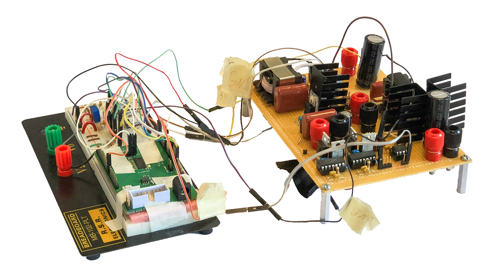
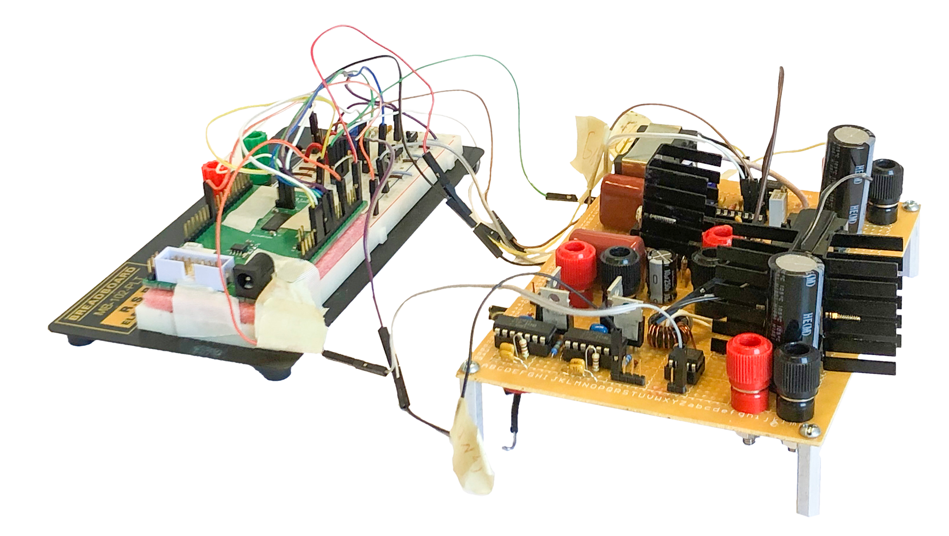
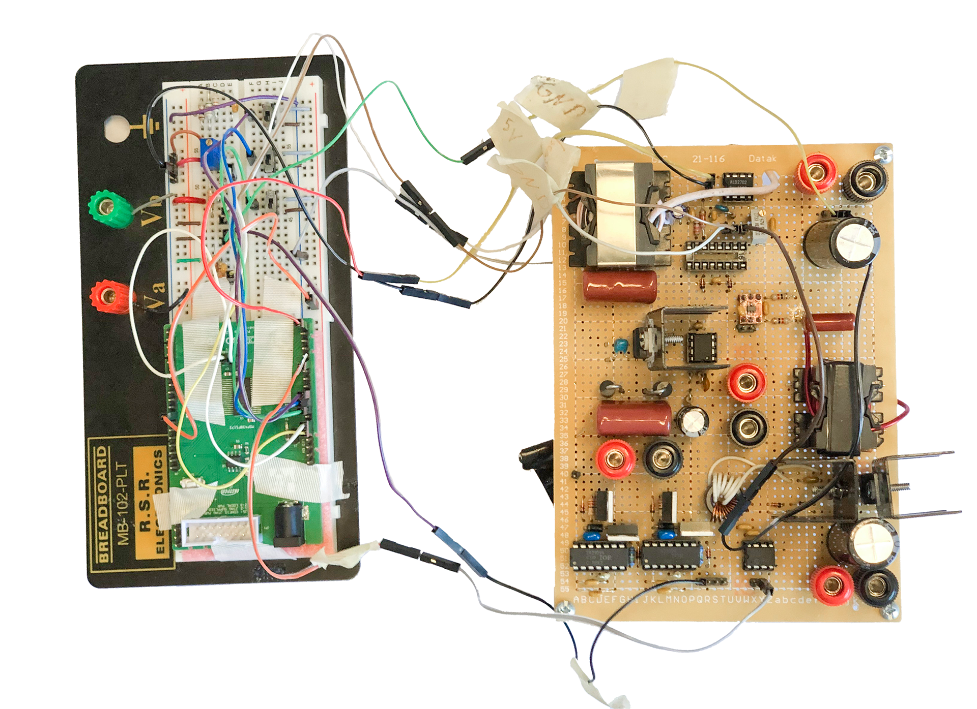
The PV system project was part of a lab in the spring of 2018. In this project another student and I designed and built a complete PV system's power electronics. A buck converter implementing a maximum power point tracking algorithm charged a 12 V battery from the PV panel. A coupled inductor boost converter then stepped the 12 V battery up to 200 V and an inverter then converted this to a 120 V RMS square wave. In an exposition at the end of the semester our system was the second most efficient among all groups.